Y2 Project Week 4
Members:
Qinglie Zhu, Zheng Zhao, Junhao Zhu, Zhiyuan Zhang
Advisor:
Valerio Selis
In last week, the biggest problem we countered was that the voltage gain of the amplifier circuit was not high enough, which was only 30. Consequently, the sound signal cannot be displayed normally on the oscilloscope and therefore the arduino could not read the correct analog value. In this week, our most important task is to think about a method to increase the gain. Additionally, we planned to connect the buzzer to the arduino and compile the code so that if the sound level transcends the threshold, the sound monitor system will warn the user.
Experiment:
1. Increase the gain of the amplifier circuit
We came up with two methods to increase the gain of the amplifier. Firstly, according to the research, the gain of LM386 amplifier can be set from 20 to 200 using a resistor and a capacitor across pin1 and pin8.

Figure1: The configuration of LM386
However, after the resistors with different resistance were connected, we found the gain was not changed and the result was same when we used different capacitors.
The other method was that we can cascade another amplifier circuit to the first amplifier so that the gain will be much higher. After connecting the circuit, we used oscilloscope to find the gain and it finally stabilized at 240.
2. Connect the buzzer
The project requires us that if the noise is beyond a threshold the system should be able to warn the user. Thus, we decided to use buzzer to realize this function. The buzzer used is shown in Figure2.
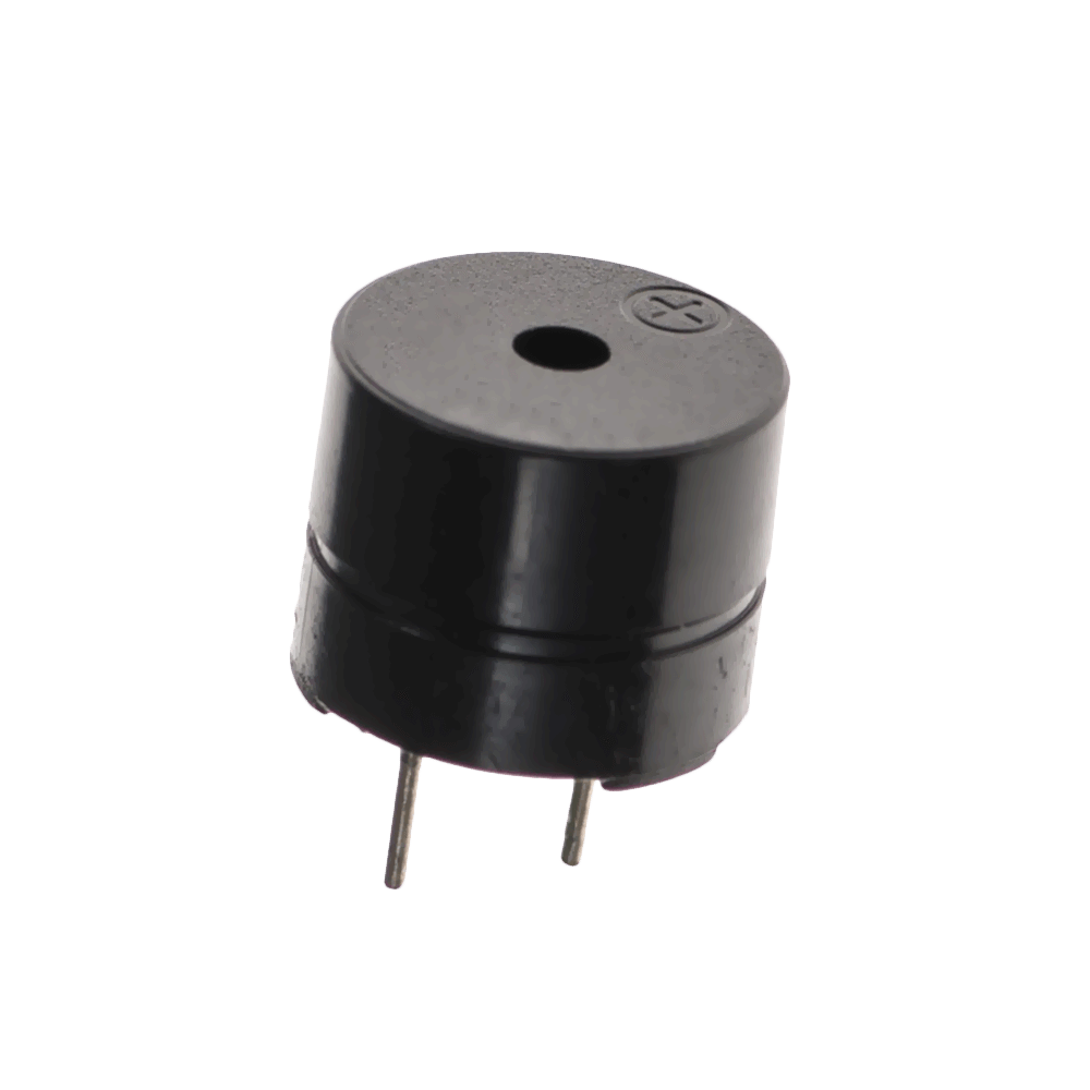
Figure2: Buzzer
The code was quite simple. If the dB value is higher than a value, the buzzer will make a sound until the dB value turns down. To make it more interesting, we found a code which decides the tone of the buzzer (shown in Figure3) so that the buzzer can play a song rather than just buzzing.

Figure3: The code of deciding the tone
To enable the buzzer play the song, we set two arrays which decide the tone and duration of each tone, respectively. The code of the buzzer is shown in Figure4.

Figure 4: The code for the buzzer
Difficulties:
After connecting the circuit and compiling the code, we conducted the test to check whether the sound monitor system can work normally. From the LCD display, we found that when nobody talks to the microphone the dB value is about 45 (because other students talked in the lab), which seemed right. However, when someone shouted loudly to the microphone, the dB value is only about 52 or 53, which was not what we expected. We searched that the sound value of normal conversation should be over 60dB. After discussing, our team thought that the problem might be caused by the formula we used which aims to convert analog value to SPL (sound pressure level). According to the reference, there should be a reference value in the formula but we did not have it and therefore discarded it in the formula. We thought this could lead to that the dB value is highly inaccurate when analog value is high. After discussing with advisor, we found a feasible method to convert analog value to dB. We can use a smart phone app called Sound Monitor(Figure 5) to calibrate the SPL with corresponding analog value.

Figure 5: Smart Phone app - Sound Monitor
Conclusion:
In this week, we solved the problem of insufficient gain and successfully connected the buzzer. However, we still need to work on calibrating the SPL so that the sound level can be more accurate.
Comments
Post a Comment